Yesterday I did try to publish a post but blog spot was not working good. I did get my windows from Marco his shop were they were cutout. They also made some iron work. When I got home I glued the wedge in front of rudder case in place and glued some piece to my motor mount. The Spinlock gas throttle was a little modified, normally the small spacers were in place but I did need some more room for the panel.
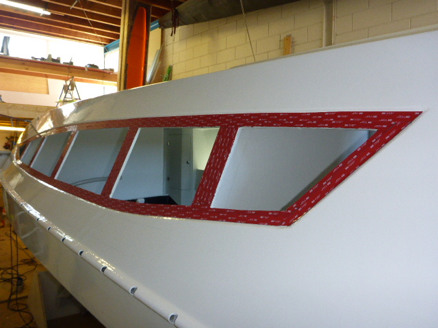
Today I drilled the holes for the mast raising support. I made them like the F22 and the F32SR on the sides. I had to look at some old photo's to see were I did put the HD foam. There have to be place some U bolts in front of it to make it complete. After that was done I started with taping the 3M VDH tape in place were the windows will come. My window is in three pieces with 5 mm between them. In the afternoon we first put the windows in place with some duct tape to position them on the right spot. I made some spacers from 5 mm thick plastic witch could be placed between the windows.
We then removed one window and pulled of the plastic from the tape and the window. I put the spacer on the tape against the other window and now we could easily position the window in place.
When the widows was firmly pushed I removed the spacer and moved to the next window. First pull away the plastic, put the spacers in place again and place the window. Tomorrow we put some silicone kit in the edges. As last job for today we put some HD putty in the edges of the motor mount.


 I started the day with drilling holes for the motor mount to fit on the rail, this did take some time because the tolerance for the holes is small. When that was done I started with the remote rudder post, I make this out of a 40 mm PVC tube with carbon around it. In this tube fits a 32 mm PVC tube and in this on fits a 25 mm steel tube. The post fill be fitted under the traveler. After the lunch I started with the bailers for the water ballast tank, I had to modify one because that one will be fitted the other way around to fill the tank. I drilled the valve away. I drilled the holes to the outside and counter sunk them on the outside. Then Fetske did arrive with some stuff from Farrier marine, I had order some tubes and bushes. We first did a tea break and I then glued the tube in place, Fetske had to do some shopping and would return with some winches for on the cabin roof. In the meantime I did some clear coated epoxy in the water ballast tank. When Fetske did arrive with the winches we mounted them with some Sikaflex. I later came to the conclusion that the bolts were a bit to long so they have to be shorted later. Fetske did some cleanup of the shed because our parents come to visit tomorrow and it is always better working in a clean space.